Saltcorner
By Bob Goemans
By Bob Goemans


Before going further, one of the most misunderstood terminologies associated with filtration equipment is 'Turnover rate!' It is sometimes erroneously described or thought of as gallons per hour (GPH), nevertheless, just how much of the systems water is actually recycled within the defined time period depends on location of the equipment's intake and outflow piping, the equipments internal flow path (turns and angles), flow paths inside the aquarium, and its height placement in relation to the aquarium. One thing for sure is that flow rate, without using mathematical equations is more guesswork than an accurate statement. More on this when you read about protein skimmers!
Lets now take a look at the following equipment designed specifically to support various filtration processes. Each type of equipment will discuss its function and how it operates.
(Please keep in mind all underlined word(s) are linkable files – just click on them and be taken to its content/photo. Also, all shown photos are clickable, which often allows a larger file to be seen.)
Undergravel Filter
The Undergravel Filter (UGF) has been an efficient and inexpensive biological filter for many decades. In fact, I owned the first one in the United States in 1950 as explained in 'About the Author,' and again here in part - At that time I was very young and a member of the Jamaica Aquarium Society in Queens, New York. At monthly meetings my questions always centered on natural looking aquariums and how to improve their water quality. The answers in that timeframe were always water changes and a good growth of live plants. To some extent, still good advice these days.
At one of the meetings a guest speaker who had just come from Europe showed a new device that could draw water through bottom gravel. He said it would result in a healthier aquarium. The item was called the 'French Invisible Filter.' It was made by a gentleman named 'French' and 'Invisible' because its porous tube-like body would be buried in the substrate with only its clear chamber-like portion containing an airstone remaining above the substrate surface. The speaker said this was the first showing of this item in the United States and he thought it might prove to be a major improvement in aquarium keeping, and how right he was!
The gentleman had only two such devices with him and was kind enough to offer one for the night's auction before returning to Europe the following day. I was the only bidder and purchased the item for twenty-five cents, which was big money for me in those days as I can remember a newspaper at that time costing two cents! After purchasing this 'filter' it was placed in my 10-gallon aquarium within a few inches (7.5 cm) of the front glass and connected to an air pump. Within a month the dark line of detritus just below the gravel's surface became much less visible. In those days all I knew was that waste products were being removed somehow and my aquarium looked cleaner, and it appeared I had a healthier environment for my guppies. At a following meeting I was asked if I thought the filter was working as discussed in the previous meeting and then explained what changes I had seen. But was laughed at by many of the 'experts,' nevertheless, over the next few decades the undergravel filter experienced design changes and became a standard and quite useful aquarium accessory.
.jpg)
.jpg)
The UGF is of course no longer tube-shaped and has for a very long time used a slightly raised perforated plastic plate that covers the aquarium bottom. Its upper surface holes or slots are small enough to prevent gravel, which is placed on top of the plate, from falling through yet large enough to allow water to easily flow through its numerous openings. Each plate also has one or more vertical water flow tubes that can be equipped with an airstone or powerhead, which push or pull water through the tube, thereby producing a water flow through the gravel covering the plate. It's this flow that delivers oxygenated water to nitrifying bacteria living on the surface of the gravel particles.
Unfortunately, these gravel particles act somewhat like a mechanical filter trapping waste matter. Therefore, monthly gravel cleaning using gravel vacuums is highly recommended to keep the gravel clean. And gravel (substrate) depth should be limited to 1 to 2 inches (2.5 - 5 cm) in most applications and be course enough, about 5 - 6 mm, so as not to fall through plate openings.
Powerheads can either pull water upward through the vertical flow/lift tube(s) or push water downward. When water is pulled up the tube, thereby drawing water downward through the gravel bed and under the bottom of the plate towards the lift tube, the UGF system is referred to as a conventional UGF system. When water is pushed down the tube, thereby forcing water to flow up through the gravel bed, it is referred to as a reverse-flow UGF system. There is some thought a reverse-flow system is slightly more beneficial than a conventional UGF system because dissolved oxygen is present at both the lower level of the substrate and at its upper surface where it meets the systems bulk water, thereby enabling nitrification at both areas. Nevertheless, both methods consume dissolved oxygen and return deoxygenated water back to the bulk water. Without additional equipment providing aeration, UGF equipped systems using powerheads to drive its circulation water always have a somewhat low dissolved bulk water oxygen content. Said condition can negatively affect animal health, therefore, it's a parameter that should be monitored and corrected as required.
Air bubbles from an airstone located in the bottom portion of the lift tube can be used to raise water inside the tube, and it will exit at the aquarium's water surface. This upward flow in the tube causes water to be drawn down through the substrate, which provides dissolved oxygen to the bacteria living on the upper gravel particles. At the same time, aquarium water surface turbulence occurs where water exits the lift tube, resulting in replenishing some of the dissolved oxygen used in the nitrification cycle. An additional benefit at the exit of the lift tube is the removal of some phosphate from the aquarium water, as the spray can leave a salt deposit heavy in phosphate (if present), helping somewhat to reduce this unwanted compound. No doubt messy, but somewhat effective. Keep in mind small bubble airstones move more water than large bubble airstones, yet they do clog faster than those producing large bubbles.
Some hobbyists questioned the value of the UGF filter when easier to use fluidbed filters (described below) came about. Actually, the major difference between them is in their physical size and ease of use, as both basically accomplished the same filtration aspects with both resulting in somewhat low levels of dissolved oxygen being returned to the aquarium. Yet, as mentioned above, when airstones are used, its effluent dissolved oxygen content would be higher than flow from a fluidbed filter.
Even though there have been many updates to biological filtration methods over the past decade, this form of filtration equipment still has some valid uses, both in the marine and freshwater hobby. In fact, a newcomer preferring to begin with a very simple small system might be better served using this equipment to set up his or her first aquarium. That way, they can become experienced in some husbandry basics before moving on to more complex and expensive larger systems! In fact, the equipment is still easily procured, inexpensive, and basically easy to use. Nevertheless, there are some precautions those using it for the first time should be aware of.
Operation Parameters
For those that still use or want to use the UGF, most consider it a piece of equipment that needs little attention once it is up and running. Nonetheless there's not one piece of equipment that doesn't need some form of attention or maintenance. Sometimes what is needed is caused by improper set up or the lack of understanding its normal maintenance requirements. Where UGF systems are concerned the following are some reasons why they may not be as successful as they could be:
CAUSE
1 - The gravel bed too deep.
2 - Improper gravel grain size.
3 - Insufficient or excessive water flow.
4 - Failure to vacuum/stir gravel periodically.
5 - Too much surface area of the gravel bed covered by rocks or other decor.
CURE
1 – A fairly level gravel bed of approximately 1 - 2 inches assures more efficient microbial filtration since anything much deeper restricts water flow thereby limiting/reducing the flow of dissolved oxygen to bacteria living on the gravel particles.
The key words there are 'fairly level,' as aquarium substrate is usually never completely level throughout the entire aquarium because animal intervention or water currents sometimes create peaks and valleys in the sandbed. But increasing water flow rates to get water through deeper areas defeats the contact time necessary for bacteria to get oxygen from water rushing pass them in the shallower areas.
Regrettably, some hobbyists think a deeper bed provides more area/particles for bacteria colonization, however, that is an invalid assumption when it comes to overall filtration efficiency, and can lead to encouraging unwanted forms of algae or the production of toxic compounds. Simply put for now, as it will be explained in detail in the following section, there are different types/classes of bacterium and their efficiency relates to their oxygen supply or lack of it, which in turn relates directly to the physical grain size and its depth. Therefore substrate depth here is an important factor
2 - Small gravel particles may clog/block water flow through plate holes/slots. The result can be little or no useful biological filtration and/or the possibility of dangerous compounds such as hydrogen sulfide building up in the little or no flow areas. Too large gravel particles allow detritus to slip through and collect under the UGF plate. A heavy accumulation of detritus under the UGF plate will eventually reduce overall water quality and also increase system nutrient content thereby encouraging unwanted algae growths.
Oyster shell and other types of crushed seashell mixes contain flat-sided particles that can easily cause poor water flow and/or channeling. Correct particle size is about 5 - 6 mm having a more rounded shape and rough surface, which allows for better water flow and bacteria having a surface they can more easily grasp/hold on to.
3 - Whether the lift tubes are powered by an air pump or powerheads the volume of water flowing through the substrate should be approximately 6 to 8 times the volume of the aquarium.
4 - Vacuuming the substrate is a good maintenance practice as it limits the build-up of unwanted detritus in the gravel and from finding its way to beneath the plate. Once a month is a good schedule for this type maintenance. Also recommend gently stirring the gravel once a week with a rod/stick, as that prevents accumulations of unwanted matter from clogging certain areas where through-flow may be less than in other areas. The stirring also frees-up some organic matter thereby allowing it to enter the aquariums bulk water and possibly feed some of the invertebrates in the aquarium or be carried by water currents to a mechanical filter if so equipped.
As for the area under the UGF plate, it will eventually collect some detritus. How much depends upon system bioload and how clean one keeps the substrate. Because it's so inaccessible it continues to become a depository for waste matter. If the aquarium has a clear bottom and is on a stand where the aquarium bottom is visible, the build-up of detritus can be monitored. Unfortunately cleaning this area has been limited to tearing down the entire aquarium and starting over or trying to flush or siphon it out. All are extremely difficult and time consuming tasks to say the least. Therefore it's better to keep the gravel as clean as possible than struggle with trying to siphon/flush out the underside of the filter plate or having to start over.
5 - Covering too much of the upper gravel bed surface with rock or other type decorations simply blocks water flow through the gravel. This reduces or eliminates nitrification in those blocked areas reducing overall biological filtration. It may also lead to anaerobic conditions, which can be detrimental to overall system wellbeing. The cure goes without saying.
Trickle Filter
Whatever form this equipment takes, e.g., hang-on-back, a stand-alone unit, or built into the back wall of the aquarium, the trickle or wet/dry filter as many call it, must be credited for the proliferation of reef aquariums. Even though there was isolated use of this biological filtration system in the 70's, (deGraaf 1973; Moe 1973), it wasn't until the mid 80's the benefits of the equipment caught the attention of average marine hobbyists.
When George Smit's articles on the benefits of trickle filtration appeared in Freshwater And Marine Aquariums (FAMA) in early 1986 the reef aquarium hobby, as it is known today, experienced tremendous growth because it resulted in an improved marine aquarium environment, much better than what occurred in UGF systems. It is often said Smit's articles generated such interest that they could be thought of as initiating the reef aquarium hobby!
The trickle filter is usually composed of three separate units: the prefilter; trickle section; and sump. Aquarium surface water first flows into a skimmer box or sometimes called a prefilter unit that hangs on the upper back of the aquarium. The mechanically filtered water then flows via gravity into the top portion of the main trickle filter unit, usually located in a space under the aquarium. When there, it enters some sort of distribution system, most often a stationary sprinkler pipe and is distributed over the surface of a drilled plate. This 'drip' plate is usually covered with some sort of mechanical filter medium. Water drips through the plate and enters the below trickle section where it flows over and between packing media that fills most of this section. This section of the unit is usually referred to as the 'dry' portion of the equipment because the media is not submerged. The majority of the biological filtration and gas exchange in this type equipment occurs in this section. The trickling of water in this so-called 'dry' section provides oxygen to nitrifying bacteria living on the surface of its packing media. This results in an effluent that is high in dissolved oxygen and nitrate. When the water exits the bottom of the trickle/dry section it flows into a large open container-like unit referred to as the sump or 'wet' section. This portion of the equipment is usually large enough to hold other filtering aids and a pump to return the water to the aquarium. Lets now look at each portion of the equipment more closely.
Skimmer Box/Prefilter
.jpg)
The skimmer box/prefilter, sometimes called a siphon box, is where water from the aquarium starts its journey to the other components of this type equipment. Even though this box can be thought of as a prefilter, its real purpose is to transport surface water from inside the aquarium to the top of the trickle section usually located below the aquarium. These units are mainly designed as a siphon box that sits on the inside and outside top edge of the aquarium. It also functions as a surface skimmer and can serve as a prefilter.
It benefits the aquarium in three ways. It first helps to remove surface scum allowing for a better air/surface water interface resulting in a better gas exchange. Next, this surface scum removal actually allows for upward flows in the aquarium that helps bring surfactant compounds towards the surface, improving the chances they will ultimately be removed by the wet/dry or with a protein skimmer if so equipped. Thirdly, the upward flow of water is replaced by a downward flow of oxygen rich surface water to the animals near the aquarium bottom.
As aquarium surface water flows into the inside portion of the siphon box it is withdrawn from this area by a U-shaped siphon tube/device and is transported over the edge of the aquarium into its back section. Water in this area then often drains through a mechanical filter, usually a sponge filter, and flows via gravity downward through a connecting hose to the top inlet of the main trickle filter section.
Keep in-mind the diameter of the siphon tube and that of the connecting hose must be large enough to keep pace with the volume of water returned to the aquarium from the sump pump. If more water is returned to the aquarium than what can be siphoned out, the aquarium will overflow. Siphons also have a way of collecting air at the top of their curved tube, and if the air bubble gets too large, the flow through the siphon tube will be reduced or stopped. This will result in more water entering the aquarium than leaving! Usually resulting in wet carpet time!
A short piece of airline tubing inserted through the inlet side of the siphon until its end reaches the air bubble can be used to suck it out. The end of the airline tubing you're holding could also be connected to the small air inlet on top of a powerhead which in-turn will suck out the bubble(s). Some siphon tubes have small air release valves built into their curved section, and when opened, allows the air bubble(s) to escape. You get what you pay for. The 'C' Siphon from CPR (shown in Chapter 2) and those from Life Reef (shown here) automatically control aquarium water level, muffle the sound of draining water, and remove accumulating air in its siphon. They are good choices when it comes to an almost maintenance free siphon box.
Keeping its mechanical filter media clean is also important, as dirty filter media can restrict water flow to the trickle filter below and cause an overflow condition in the aquarium. Some siphon units use a section of hollow sponge that surrounds its drain connection. When the sponge becomes clogged, water simply overflows the top edge of the sponge and flows into the drain line.
The sound of water entering the drain tube can, in units of less quality, be somewhat noisy. If the drainpipe is removable, drilled many holes in it, as drainage will then be somewhat quieter as it divides the entering flow. Furthermore, some trickle filters are sold without a siphon/prefilter. If so, it gives you an excellent opportunity to select a high quality unit that will provide the needed performance mentioned above. And if an overflow is purchased separately, make sure it will adequately handle sump pump water flow. All in all, prefilters are fairly simple devices and require little maintenance.
Trickle Section
Now that the water has left the aquarium the how it's going to be dispensed over the packing media in the 'trickle' section is the next subject needing some discussion. As with almost any equipment, it goes through various design stages. Those who are trying to improve the product generate some design changes, while others are simply trying to make it less expensive to produce. Lets review two forms of irrigating methods — rotating or that of stationary sprinkler pipes, which ultimately allow water to drip evenly (hopefully) over the packing media below. Both have some interesting history.
There were various trains of thought when it came to making a choice between the two irrigation methods. Early in their design many hobbyists reported that when plastic ball type packing is utilized some rotating sprinkler bars did not throw the water far enough to reach into the corners of the square-shaped trickle chamber. Therefore the packing in corner areas never become wet and failed to become colonized with nitrifying bacteria, defeating a portion of the system. In other cases, complaints had the rotating sprinkler pipe rotating too fast and throwing the majority of the water to the sides of the container. This allowed most of the water to run down the sides of the trickle section never wetting the central packing. Where a roll of double layer spiral (DLS) material was used as packing and there was even-distribution of water, some water dripped down in corner areas where it couldn't come in contact with the roll of DLS. Therefore, plastic ball-shaped packing was thought to be a better choice in systems equipped with a stationary sprinkler pipe and a correctly rotating sprinkler pipe might be a better choice in systems that utilize rolled DLS. Nevertheless, the additional cost factor associated with rotating water distribution tubes and the fact the stationary distribution method required less maintenance has made rotating systems a rare find these days no matter what type media is used!
Keep in mind it's always wise to locate the trickle section in a dimly lit area to prevent algae from growing on and clogging its packing/media. Algae growth in this area can cause channeling of the water and defeat the purpose of the unit, which is to evenly spread trickling water over its media surfaces to encourage nitrifying bacteria growth on them.
Trickle Packing (Bio-Balls)
.jpg)
The most important trickle filter efficiency factors are the amount of surface area on the packing media below the drip plate and as explained above, the even distribution of the water flowing over it.
As for packing, their most popular form has been the ball-shaped plastic media that got their start in air and waste treatment facilities. Most of this media, properly called 'packing,' were engineered to remove pollutants from smokestacks or sewage treatment plants. Since it can provide surface area for the colonization of nitrifying bacteria, even those designed for smokestacks, it progressed from their original function into the aquarium trade. When used in aquarium trickle filters, the ever-moving thin film of water over the packing surface quickly replenishes the oxygen used by nitrifying bacteria living on its surface. And, since this packing doesn't wear out, they are very cost efficient and need little or no maintenance. Therefore, nitrifying bacteria living on the surface of the media receive all the oxygen they need and because of the trickling effect, highly oxygenated water flows back to the aquarium. Of course this is not the case in the UGF system or the fluidized bed sand filter where oxygen is removed by bacteria living on the fully submerged gravel or sand particles, and the water flowing past them returns to the aquarium minus some of its oxygen.
Whether this plastic material is shaped like a sphere, ring, cube, or whatever, 'surface area' is its most important criteria for determining their cost effectiveness. And surface area is generally measured in square feet on the total number of individual packing that will fit into a one-gallon container. What constitutes how many gallons of packing are needed to support a given size/type aquarium has always been a good question and you'll probably find that almost everyone has a different answer.
My rule-of-thumb is that a gallon of packing containing 10 sq. ft. of 'useable' surface area is the minimum needed for every 10 gallons of water in a fish-only aquarium. This is based upon my personal experience in my fish-only systems. Depending upon the surface area provided by the brand media of your choice, the number of gallons required to meet a system needs must be adjusted. For a heavily loaded fish-only system I would increase the recommendation to 1.2 gallons of packing per ten gallons of water. As for their use in a reef aquarium the 10 sq. ft. of surface area should be applied to 20 gallons of water. (Yet prefer this type equipment not be used on complex reef systems because of the nitrate produced.) Usually, the packing manufacturer or distributor should supply the data as to square feet of surface area per gallon of media.
Unfortunately, this does not tell you if the surface area is 'fully' useable, which depends upon packing architecture/physical design. Keep in mind packing should be constructed so it becomes fully wet. This 'wettability' factor is extremely important, as nitrifying bacteria will not colonize a dry surface. There are no charts or rating factors for wettability that I know of, so I find the human eye to be the best judge and personally prefer the architecture of the ball-shaped packing, which I have used in many of my aquariums.
Void space, the ratio of how much area is actually occupied by the packing structure and the space for water and airflow through the individual packing, is another fairly important criteria, as it denotes good distribution of water and airflow. In the past some packing makers claimed void space to be an important ability of their product to degas ammonia. After many discussions with environmental engineers on this subject, none believed this possible in the size equipment used on home aquaria. These same engineers choose ball-shaped packing for their very large commercial stripping towers because of their excellent wettability and water/airflow characteristics. In fact, all agreed that a structure 8 feet high with a large volume of airflow would be required before even minute amounts of ammonia could be degassed. Nevertheless, all in all, the water and airflow must be evenly distributed throughout all the packing that fills the trickle section. Any type packing that would contribute to channeling, i.e., the concentration of either water or air in streams instead of even and sheet-like distribution, would distract from its cost effectiveness even if it had greater surface area or higher void space than other type packing.
There's another factor to consider when wanting to gain the most efficiency from the selected packing and it's the application of an outside airflow through the packing. By placing one or more airstones under the column of packing, dissolved oxygen in an aquarium can go from unacceptable to saturation. Of course, when one does this the top of the trickle tower should have a vent hole for the additional air to vent/flow outward.
Some hobbyists are under the impression that by putting gravel or packing in the sump they can increase the biological capacity of the trickle filter. Well, think of all the trapped particulate matter breaking down into unwanted compounds this is going to cause in this area! If that is not reason enough not to place gravel or packing in the sump, consider the myriad of bacteria living on the surface of this material and the amount of oxygen they consume. In the trickle section the oxygen is being replenished as water flows over and past the packing. Not so with submerged packing! The additional oxygen the trickle section delivers to the aquarium is one of the main reasons this type equipment is purchased. Why defeat it by having what is usually an unneeded large community of oxygen consuming bacteria living in the wet section. There are some other important aspects to look for in a quality made 'wet' section, and they are listed in 'Features' below.
Double Layered Spiral (DLS)
This form of trickle section packing is white polyester material sandwiched between layers of black woven plastic. Even though rarely found these days, it still exists in some countries and for that reason is discussed here.
When new it has greater surface area for the same given space taken up by plastic ball-type packing. It also allows for good airflow; does not restrict water flow; distributes water very evenly; allows for greater contact time; and, is less expensive than plastic type media. The key words there are 'when new.'
Unfortunately DLS can quickly become coated with detritus and become a mechanical filter instead of a biological filter. Prefiltering the water that passes through DLS helps diminish but not eliminate this detritus buildup. Therefore, the buildups of detritus or algae require this product be periodically cleaned. Yet even the gentlest cleaning methods will wash away much of its nitrifying bacteria since the material is very smooth and bacteria have no firm grip on its surface. It may be weeks before it becomes fully recolonized.
The biggest problem with DLS may be that it's used as a 'roll' of media. My personal opinion is the media should be sliced into pads, similar to slices of bread in a loaf. Then, the entire trickle section could be filled with vertical slices' of DLS, which would also eliminate the open corner situation in the trickle tower. This would allow for the removal of one or two slices per month for cleaning without radically affecting overall efficiency of the entire filter as would happen if the entire roll were removed for cleaning. A roll of DLS that is .5 inch thick, 10 inches high and 25 feet long is said to provide biological filtration for an aquarium up to 100 gallons, or that of 15 cubic inches per gallon.
There are some other considerations to take into account when using this inexpensive media. First, the physical shape of the material makes it somewhat inefficient in high water flow areas. Because of water shear, i.e., the force generated by flowing water, nitrifying bacteria can be washed off its thin string-like surfaces. Therefore I recommend not using DLS in systems where there are high flow rates. Also, since DLS appears not to degas carbon dioxide as effectively as most plastic packing media, prefer to utilize this media in aquariums where macroalgae will be one of the more desired species. One other factor to be considered is its initial cost. DLS is very inexpensive when compared to most plastic packing media, but will not last indefinitely (you know what I mean) as will plastic packing. DLS will no doubt have to be replaced in a few years, increasing overall cost of the system and increasing time spent for general maintenance.
Bio-Bale Media
This plastic media is a common replacement for DLS or bio-balls in many trickle filters because of its very low cost. Its narrow, yet flat surface is twisted into a mass of loosely entwined lengths. In systems where my clients or I have used it, we experienced the same drawbacks as mentioned with DLS. To resolve this in one system its trickle section was divided into four vertical sections, each filled with Bio-Bale. This greatly reduced channeling and also allowed removal of 'sections' for cleaning.
Keep in mind; just as it is preferable to maintain a constant upward airflow throughout a column of ball or DLS media, it is also preferable to supply a flow of fresh air up and through this type media. This can be accomplished by simply placing one or two airstones under the trickle section. Dissolved oxygen tests have shown that a single airstone located in this area could raise dissolved oxygen by approximately 1.0 ppm in some cases!
Features
All of the embellishments noted here will probably not be found on any single brand trickle filter. If they were, some might not be used or even needed and only unnecessarily add to the units cost. But the hobbyist could install those of interest if fairly handy with tools.
Finally, keep in mind their effluent contains some nitrate, as that is the result of the nitrifying bacteria living on their packing material. This is generally not a major problem in some fish-only systems, but must be taken into consideration if used on reef aquariums, where nitrate is one of the compounds its keeper always wants to minimize.
Canister Filter
.jpg)
This is a very simple, freestanding, efficient and functional piece of equipment, usually somewhat cylindrical in shape and equipped with a small, epoxy-sealed low electrical consumption motor. They were developed in the 1970's and early 1980's and have proven to be especially good for chemical filtration. Most modern units usually have three or more separate internal baskets/areas that can be filled with media designed for mechanical, chemical, and/or biological filtration. Some have self-priming features, many use convenient quick disconnect valves, and some units even come with an internal UV sterilization lamp. Samples of media designed to fit these baskets, e.g., sponge filter pads, sacks of activated carbon, and plastic packing for biological filtration, are often supplied with the new unit. Replacement media is readily available at on-line aquarium product companies, or found sometimes at local shops.
Optional attachments are available with some models that can increase their efficiency, e.g., various strainers to attach to the end of the intake pipe; foam prefilter devices to fit over the intake pipe opening; surface extractors to gather water from the surface of the aquarium; and, spraybars that distribute return water via small drilled holes along the length of their hollow tube and can be located at any angle in the aquarium via suction cups. Nevertheless, they add additional maintenance to these type filters, as they tend to need monitoring more often then the filter itself/changing its internal media. As for canister filter location, they are usually placed on the floor near or below the aquarium, as their supplied tubing is generally limited to about 6 - 10 foot lengths and their small internal motors are not capable of raising water too high. To maximize efficiency the location of its intake should be as far as feasible from its return water outlet. Therefore the just filtered water will not be immediately drawn back into the filter.
When it comes to 'purposely' using any basket within these units for biological filtration, it's my opinion that should be considered a not needed function unless the aquarium has no sandbed or live rock, and/or is somewhat overcrowded/overfed. Then any additional biological filtration may help, nevertheless, biological filtration in a canister filter removes dissolved oxygen, and therefore, the retuning water is poorly oxygenated. Since needing additional biological filtration is rarely needed, my preference is to use that basket for additional chemical filtration since the canister filter excels in this process since all water flowing through it must pass through its media, which is exactly how chemical filtration should be accomplished. And where reef aquariums are concerned, unwanted algae nutrients such as phosphate can be easily controlled when using chemical media designed for this purpose!
Keep in mind when loading these units with media it's recommended the coarsest media come in contact with the incoming water first, then the next finer media and so on. This way the largest incoming debris will first be filtered out with progressively smaller debris in the following media. This maximizes water flow and minimizes clogging. For example, when in the past I used canister filters having three internal baskets, I first filled the lower basket with activated carbon (often use either ESV or Boyd Chemi-Pure) in a sack of course, and also cut up a Poly-Filter into small pieces (More areas of absorption that way). That filled the first basket. In the middle basket I placed a layer of filter fluff and spread five tablespoons of ROWAphos phosphate removing media (a very finely grained material) over the filter fluff. Then covered the media with another shallow layer of filter fluff. I did the same in the top basket and changed the media when there was the first sign of any phosphate reading on my test kit. It worked well for me!
And yes, in the above set up there is also some minor biological filtration as any area that's been wet for several days will develop some microbial processes, and of course the filter fluff would also provide some mechanical filtration as water passes through it. Nevertheless, its biological and mechanical filtration is mostly secondary processes.
If there are any drawbacks with canister filters, their effluent water temperature is sometimes a tiny bit higher than its inlet temperature. Therefore, depending upon what size unit is used on any given size aquarium, it may be a good idea to take a sample of its effluent water after its up and running for several days and check its temperature. Could be if used on a small aquarium, it may push its water temperature slightly higher.
Some newer models provide UV sterilization, built-in heaters and microprocessors to monitor performance! And for those that demand quiet operation of their equipment, they are excellent. Actually, canister filters are what I consider a 'near-perfect' piece of equipment!
Hang-on-Tank (HOT) Power Filter
These usually take the shape of a narrow box that hangs on the outside edge of the aquarium and are used to trap particulate matter and also house some sort of chemical media, such as activated carbon. In the days past, a siphon tube was used to siphon water into the box, and an air-cooled pump sat on top of the box with its extending shaft and impeller in one of the unit's water filled compartments. When the pump ran, its impeller forced water into a tube that returned the filtered water to the aquarium. These were maintenance intensive, as salt creep and noise were always a problem, as I personally had many of these type units! In fact, I can remember writing an article about how to disassemble them, oil certain areas, and use some silicone-based grease around their exposed motor shaft to keep salt creep from getting up and into the motor housing.
Today, these filters draw water from inside the aquarium with a small epoxy coated pump often located at the bottom outside of the unit, where it flows through one or more media filled chambers and finally simply spills back into the aquarium. They are extremely quite and mechanically trouble free, with replacing the filter media when needed their only on-going maintenance. Nevertheless, occasionally, maybe once a year, they should be removed, thoroughly cleaned including the motors impeller, reassembled, and restarted.
.jpg)
.jpg)
Fluidized Bed Filters
Fluidized bed filters have been used in aquaculture systems for many years. In fact, they have replaced trickle filters in some aquaculture systems as the primary biological filtration system where their cylinder or box-like systems are partially filled with quartz or silica sand and water flows upward through the media. These type units use a fairly swift flow of water to keep the media in suspension, thereby allowing dissolved oxygen to come in contact with the surface areas of each media particle. Nitrifying bacteria colonize these particle surface areas and in turn provide the same benefits as derived from UGF systems. But in this type equipment, they do so more efficiently with much less sand/gravel than what is used in the UGF because its sand particles are suspended in the upward flow and not compacted as they are in UGF systems.
Where this type equipment is used for hobbyist marine aquariums for the purpose of biological filtration, silica sand is not a good choice as this type particle has very flat-sides, which make it difficult for bacteria to colonize/adhere to. Also, where there is fairly heavy water sheer/current, nitrifying bacteria will have a difficult time adhering to the particle of almost any type surface. Also keep in mind silica sand experiences a slight solvency at a pH of 8.0 and accelerates when pH reaches 8.5. Therefore, in alkaline marine systems, silica sand can initiate brown diatom algae and is simply a substrate that should not be used for various reasons.
Of course water flow is a critical factor in this type system, as too little will not suspend particles thereby depriving bacteria of oxygen and limiting the nitrification process. Too much water flow could knock bacteria off the sand particles and also cause reduced nitrification. To control the flow, these type units come with a control valve where flow can be regulated to keep its media in suspension. They are easily connected to powerheads, which do not always come with the units, and if feasible, its water supply should be prefiltered to prevent detritus from causing channeling or clogging of its sand particles.
All in all, this is a truly simple device that requires little maintenance and requires little space compared to a trickle filter. Manufacturers claim there is more biological filtering surface area than any other type biological filter. In fact it is claimed there is about 6000 square feet of surface area per cubic foot of media. Consider it great for retailers, breeders, and any high-density bioload situations, yet keep in mind it also consumes dissolved oxygen, therefore, you might want to monitor that aspect if used in a system having a high bioload.
Furthermore, this type equipment is now more widely used to suspend phosphate and/or nitrate removing media, making them ideal for controlling these algae nutrients. These are highly efficient, simple in design, and easily cared for. In fact, there is even a fluidized bed calcium reactor – check it out at D&D Solutions!
.jpg)
.jpg)
Corner Box Filter
These are usually small plastic boxes designed to fit into the inside corner of small aquariums, and are especially useful in small quarantine systems. Some are powered by an airstone, which receives a supply of air from an outside air source, usually a small air pump. Others contain a very small water pump that provides the through flow. They can hold various types of filter media, with activated carbon and filter floss being the most popular combination. They may be well suited for the small aquarium where minimum chemical and biological filtration and/or small quantities of special filter media are needed to fulfill a special requirement. They can be mounted horizontally or vertically, and/or hidden behind decorations.
.jpg)
.jpg)
Sponge Filter
This type product provides biological and mechanical filtration, and there are various sizes and a wide range of placement possibilities associated with their use. These permeable foam or sponge filters are simply a highly porous synthetic material having a tremendous surface area that allows for the colonization of large numbers of nitrifying bacteria. On some type installations, an air powered vertical lift tube connected to the filter media draws water in and through the sponge media bringing dissolved oxygen to the nitrifying bacteria living on its large volume of surface areas. The outflow then simply returns the filtered water to the aquarium.
.jpg)
.jpg)
I've seen hobbyist fish-only aquariums as large as 125 gallons maintained solely on these type filters, with no other forms of biological filtration. In fact, these devices are extremely good for breeding aquariums and/or for quickly getting an aquarium up and running. They are reusable and inexpensive.
When the time comes to clean them after a long usage, a large amount of detritus can be released back into the aquarium when the sponge is lifted out of the aquarium. Covering the sponge with a plastic refrigerator bag and lifting it out inside this strong bag will help capture most of the waste collected on and in the sponge.
Protein Skimmer
There are many chemical filtration 'substances' packaged in one fashion or another, such as activated carbon, and sold as items that will enhance water quality. But when it comes to chemical filtration 'equipment,' the protein skimmer is in a class by itself, nevertheless, there are many differing opinions and confusing information about its value. Some say they are not needed while others say they should be used fulltime. Others say they're only required on a part-time basis, while others say they remove too many valuable nutrients. And then there are those that say the skimming process can only be used in seawater applications. The debate continues, as does the variety of skimmer designs, sizes, and prices.
And over the past couple of decades it seems like I've answered every possible question when it comes to protein skimming. Some of these were quite simple while others required research and in-depth answers. And because of that, this discussion here will go into 'overdrive' to fully and clearly make you aware of their importance! Hopefully the true value of the skimming method will then be fully understood along with how to select the proper size and type of unit. The best places to begin is with a general overview of why there is need, and then proceed to associated items of interest.
Overview
The level of dissolved organic carbon (DOC) compounds, along with other nutrients such as nitrate and phosphate, tend to increase as captive systems age. Even though they are directly associated with causing unwanted algae growth and diminishing water quality, their impact is not obvious in fairly new systems. Many hobbyists often fail to recognize increasing biological load. An aquarium with a few fishes fed once everyday may seem stable for a long period of time. Its water may appear to be clear and there is little or no unwanted plant growth. Dissolved nutrients appeared to be well below what is perceived as critical levels. Nevertheless there's the inclination to add one more attractive specimen, overfeed or allow maintenance to lag. Furthermore, bacteria are constantly being renewed, as their normal life cycle is quite short. Dead bacteria and those that take their place to a certain degree continue to add biomass to the aquarium even though the aquarist may not be adding new animal specimens.
Factors such as these can affect any aquarium relying solely on biological filtration, as once the nutrient load exceeds what the bacteria can efficiently process, it will be difficult to maintain an efficient environment, i.e., where the energy from the input of foods/wastes is used by the systems bacteria, not stored in the form of unwanted algae and diminishing water quality. When that happens, usually sooner than thought possible, the aquarist will be applying more time to maintenance than viewing enjoyment. The point here is simple, why wait until there is unwanted algae blooms or animal losses, especially in reef systems? Without understanding the root cause of the problem, temporary fixes will rarely resolve the underlying cause. And this is why the skimming process, properly used from early on is so useful, as it removes or helps to minimize some of these accumulating nutrients.
Although much of the following content on this device is steered towards usage in seawater applications, some of what is written here can be applied to freshwater systems. Its mention here because some hobbyists consider it a process not useful in freshwater aquariums, and I would agree it has limited use, nevertheless it should not be completely rejected and will discuss it briefly in the following text.
Adsorption Process
The removal of DOC compounds along with other substances can be accomplished with the use of a process called 'adsorption,' to which the skimming process excels! The process allows matter to collect or adhere on an interface, gas or solid, and be removed from solution. This physical attraction process differs from absorption (molecular sieving), which is similar to what a sponge accomplishes when water flows into its internal crevices and tunnels thereby trapping the compounds inside. The removal of DOC compounds accomplishes three effects:
1) Toxic and potentially toxic compounds are minimized.
2) Light transmission is improved.
3) Biomass is maintained in a more efficient environment.
The adsorption process also removes unwanted substances before bacteria oxidize them. With this in mind it makes a lot of sense to utilize the chemical adsorption process in addition to biological filtration so as to assist the various classes of bacterium in maintaining equilibrium (theirs and the resulting overall balance in the system). In fact, the two most significant non-biological mechanisms that achieve adsorption are protein skimming and the use of activated carbon. In my opinion, both should be used. (Chapter 6 contains details on activated carbon.)
Skimmer History
Europe has produced several aquarium equipment advances such as the trickle filter and undergravel filter, yet the protein skimmer is among the most important. European hobbyists have used the foam fractionator, more commonly called the protein skimmer, in their marine aquariums for at least a decade before it became popular in North America near the end of the 1980's. Guido Huecksedt of Germany is accredited with its first use in the late 1960's, a co-current unit.
In the early 1970's this simple device made its way to North America. The first one I saw was in 1975 at the home of a German hobbyist and was somewhat unimpressed with it because its wet foam produced an inefficient effluent. Over the next fifteen years protein skimming popularity climbed and in the mid to late 1980's it was incorporated into some of the more technically advanced trickle filter systems. Only then did American hobbyists begin to sense its true importance.
Keep in mind as the protein skimmer reduces unwanted dissolved substances, general water quality improves because it helps stabilize and boost pH, raise redox and reduce carbon dioxide (a nutrient that can encourage plant growth). It's also a device that will increase dissolved oxygen levels. Another benefit not discussed frequently is by removing some pollutants in the bulk water there is improved light spectrum in the aquarium. Photosynthetic invertebrates will benefit greatly, unwanted plant growth will not!
Even though the trickle filter (biological filtration) and the protein skimmer (chemical filtration) provide different forms of filtration, there should be no doubt the protein skimmer is a sensible filtration aid to almost every captive system. Moreover, it really doesn't matter whether you're a freshwater or marine hobbyist, as the goal remains the same — maintain optimum water quality and enhance the health of its captive specimens
The Process
The protein skimmer has been called many different names, e.g., a foam fractionator, air stripper, and foam separator. Since it removes DOC compounds containing protein, it's commonly referred to as a protein skimmer. And even though this device removes various compounds of which protein is only a small portion, the name 'protein skimmer' is somewhat incorrect. However, wouldn't want to be the person to try and change it.
As for the skimming process, Mother Nature uses it as one of her tools to care for her oceans. If it works for her it must be good for our aquariums. Even if you have never seen or used a protein skimmer you probably have seen the waves on a beach come rolling in with foam left at their high point on the sand. That foam on the beach or the foaming action on reef crests as waves crash over them is the same as what occurs inside the protein skimmer. It's this 'foam' that holds the elements and compounds to be removed.
The foaming process in nature or inside the protein skimmer occurs because the upper water layer contains a special group of unwanted compounds called 'surface-active' compounds or 'surfactants.' These compounds tend to collect near or on the water surface because they are bipolar. Their 'hydrophilic' or polar ends prefer to face water. Their 'hydrophobic' or non-polar ends are attracted to air. There's probably not a hobbyist that hasn't seen the result of this attraction to the aquariums water surface. Just in case you think you haven't it's that thin scum-like film on the water surface, which is simply a collection of some unwanted bipolar compounds.
Keep in mind these bipolar compounds naturally rise in the water column and congregate near or on its surface. It's this attraction to air that provides a way out of the aquarium for accumulating DOC compounds including toxic organic substances such as terpenoids from soft corals and Caulerpicin from macroalgae. By effectively stripping these toxins out of the reef aquarium it's possible to keep a variety of more healthy corals in a confined space.
The skimming process also removes various elements and plankton-like material commonly found in water. For example: amino acids, albumin, proteins, carbohydrates, phosphate, iodine, phenols, bacteria, phytoplankton and various heavy metals such as copper, nickel, cadmium, iron, manganese, vanadium, lead, aluminum, and zinc.
Because so much can easily be removed some aquarists have well-founded concerns about the skimming process. It does indeed remove some important elements such as iodine/iodide and valuable plankton-like material. Yet it remains unclear just how much is actually removed. As true as these concerns are, they are not sufficient reasons not to use a protein skimmer in most aquariums. Captive systems with efficient protein skimming, such as in my own aquariums and those I've seen in my travels, continue to function flawlessly with only minimum attention to these areas of concern.
In fact, for those concerned about its ability to remove some 'good' elements, there are many quality trace element additives on the market that can be added as recommended by their manufacturers. Also, small water changes prepared with a quality synthetic salt mix will help replenish most trace elements. Plankton-like additives are also appearing on the market and I've tried several of them with good results. Bottom line, the benefits provided by skimming far out weigh its small deficiencies.
Protein skimming also helps maintain a reasonable pH level in a couple of ways. First, pH remains higher when excess carbon dioxide is removed. Second, when dissolved organic compounds react with mineral carbonates the precipitant can coat live rock and calcareous gravel particles. A good portion of these DOC compounds can be removed prior to their reacting with carbonates by using the skimmer adsorption process. Therefore calcareous gravel particles may remain active longer thereby slowly dissolving and adding to the system's buffering capacity. Live rock will also benefit if unwanted algae growths are limited. Even though skimming removes a lot of nasty things, ammonia is not one of them. At the pH level maintained in marine aquariums very little to none is removed.
To accomplish the protein skimming process the aquarium water needs to be mixed with fine air bubbles and passed through a vertical column. As the tiny air bubbles rise in the skimmer column, adsorbates are attracted to bubble surfaces. When there is sufficient water flow and an adequate number of properly sized bubbles, foam is produced at the top of the skimmer column. The skimmer column where this process occurs is usually referred to as the 'reaction cylinder.' Remember the fact that many of these unwanted compounds are bipolar and they want to get close to any water-to-air interface. Because of this they adhere to the surface of the rising air bubbles, the adsorbent, which is simply the closest water-to-air interface. These bubbles, now partially coated with dissolved particulate surfactants, collect at the top of the reaction cylinder as conglomerate foam. The accumulating foam slowly overflows the top of the reaction cylinder and spills into a device aptly named a waste collection cup. The cup is emptied as often as necessary, effectively removing many of these elements/compounds from the closed system.
As simple as this may seem, success with this method depends upon the composition of the foam, which in turn depends upon a few things of which bubble size is of critical importance. Without the correct size bubbles efficiency is lost, even if other operating parameters such as column height, air volume, column diameter and water flow are correct. A bubble size of 1 mm or slightly smaller is the most effective. The necessity for tiny bubbles is two-fold. First, they have more surface area than larger bubbles because there can be more of them in any given space. Therefore they gather more surfactants than larger bubbles. Second, it's easier to keep smaller bubbles from rising too swiftly in the reaction cylinder. This adds time to their ascension, usually referred to as dwell time. Airstones and venturi devices have been used to produce the bubbles, however, other devices have entered the market and appear to be even more efficient for this purpose and are discussed further below.
To increase bubble dwell time, a downward 'counter flow' or 'counter-current' flow of water inside the vertical reaction cylinder is utilized in most skimmers. The downward flow of water, acting against the tiny rising bubbles, slows their travel time to the top of the reaction cylinder. To a certain extent, the longer the bubbles dwell inside the reaction cylinder the longer they have to come in contact with pollutants. The more pollutants attracted to their surface, the more pollutants removed. Most protein skimmers are column-shaped because it allows for better water flow and bubble contact characteristics.
There are numerous ways to create small air bubbles. A quality air pump can be used to force air through airstones and diffusers. Airstones made of hard woods such as limewood, basswood, and oak are much better at producing fine air bubbles than those made from bonded glass beads, natural porous stone, or ceramic materials. However, wooden airstones do not usually last more than a month. They tend to rot and fall apart quickly. Once the bubbles start to grow larger, airstones need to be replaced.
A very simple and inexpensive device called a 'venturi' is a superb substitute for the airstone. Using the Bernoulli principle of fluid flow dynamics, Clemens Hershel invented the venturi in the late 1800's. The venturi is basically a hollow tube with an hourglass-shaped interior. As water flows into the device its velocity increases because of its tapering interior design. This velocity increase is accompanied by a pressure reduction. At the narrowest portion of the tube's interior the flow pressure is less than outside atmospheric pressure of 14.7 pounds per square inch at sea level. Upon passing through the narrowest portion of this device the then expanding interior allows the flow to recover its original entrance velocity and pressure. By inserting a small hole as an air inlet into the narrowest portion of the device, outside air will be drawn in and mixed with the water flow. A correctly designed venturi along with proper water flow is capable of producing a large volume of extremely fine bubbles. The venturi usually requires no replacement, as do airstones.
Passing an air flow through a spinning water pump impeller is another excellent way to produce a vast amount of fine bubbles, and this method is used in quite a few of the more popular brand units.
.jpg)
Even though bubble size and their volume are important, stability and drainability of the collecting foam is also of significance. Collecting foam must remain stable (bubbles not quickly breaking) long enough for rising bubbles to push it to the point where it can slowly flow into the collection cup (Photo Credit: Life Reef). Stable foam is referred to as 'dry' foam and remains as bubbles for ten to twenty minutes at the upper edge of the reaction cylinder and in the collection cup. The dry foam generated by one of my skimmers sometimes tends to stay bubbles for hours in the collection cup. At a minimum, the foam's bubbles need to last long enough so their coating of surfactants can drain into the collection cup. If foam bubbles break within a few seconds of reaching the top of the reaction cylinder, it's referred to as 'watery' or 'wet' foam. This type foam can deposit most of its adsorbates right back into the aquarium instead of the collection cup. Extremely wet foam can also quickly fill the collection cup with mostly water. Such a condition can also quickly deplete the water in the aquarium, and depending upon skimmer location that may lead to the need for a new carpet!
There are many ways to increase skimmer efficiency, which may include increasing skimmer height or diameter of the reaction cylinder, adding a second or third airstone or venturi, or increasing speed and volume of the counter-current. Most manufacturers do a very good job at optimizing their units, nevertheless I have sometimes found efficiency over-stated in advertisements. Therefore, it's helpful to understand what makes a protein skimmer efficient so as to purchase the correct unit the first time.
Classifications
Generally, most protein skimmers are placed into three different categories: co-current, counter-current, and power skimmers. Co-current and many counter-current models are fairly straightforward in design. Power skimmers generally fall into a category requiring stronger water pumps and those incorporating very efficient cutting edge designs. Let's take a brief look at each.
Co-current
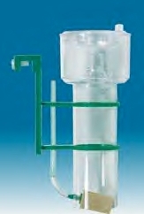
The co-current skimmer, such as the Sander Piccolo nano skimmer, is usually located inside the aquarium, and in my opinion, is the most simple, least expensive, and least efficient of skimmers in todays marketplace. It's usually driven by a single airstone located at the bottom of the unit. Air bubbles rise inside its vertical column and foam is produced at the top of its reaction cylinder. The foam then spills into its collection cup. Aquarium water is simply drawn into the open bottom of the skimmer column by rising air bubbles. Since there is no counter-current, there is short dwell time for rising air bubbles. Some DOC compounds are adsorbed, but efficiency is very limited because the foam is usually unstable and very watery. Co-current skimmers are rarely seen these days since their time has mostly come and gone. However, even a co-current skimmer would be better than no skimmer. (Photo Credit: Unknown)
Counter-current
.jpg)
Counter-current skimmers, whether equipped with airstones, venturi, needle wheel or another method of introducing an air source form this very general category, and most skimmers sold these days fall into this category. Tall models are usually remotely located and shorter models may become part of some other type of equipment such as a trickle filter. To generate a counter flow in relation to the rising air bubbles, water flows into the unit near the top of the reaction cylinder and flows out near its bottom. Its air source is located at the bottom of the reaction cylinder and supplies fine air bubbles that struggle to rise against the downward flow of water, hence the term counter-current. The overall efficiency of these type skimmers is greatly increased by extending their bubble dwell time.
Power Skimmers
.jpg)
Some also utilize counter-current flow dynamics, however they, i.e., brand/models differ mainly because they apply additional methods to enhance bubble volume and dwell time. Some power skimmers pass a water-to-air mixture through a powerful water pump and then inject it into the reaction cylinder in a swirling vortex pattern. There are other types of power skimmers on the market that do not use a venturi, such as the aspirator driven and the forced water downward flow models.
The aspirator driven skimmer draws outside air directly to the water inlet side of the skimmer pump. The pump's especially designed impeller cuts the airflow into very fine bubbles and the now water and bubble mixture is delivered to the bottom of the skimmer's reaction cylinder. This process is simple and efficient and can be applied to different size water pumps to fit a wide range of flow rates and skimmer sizes.
Many aquarists consider forced water downward flow models as top-of-the-line models and are referred to as 'downdraft' or 'high speed aeration' processes. Downdraft skimmers are equipped with strong water pumps to force water down a narrow column filled with plastic bio-media in some models. The crashing of water against the media is similar to waves crashing over the fringing reef and creates a saturated fine bubble-to-water mixture that then enters a standard skimmer body.
Another downward flow model referred to as high-speed aeration, forces water downward through a bulbous-shaped device (Beckett valve) at the top of the skimmer unit. A large amount of air is sucked in through this device and as it enters the downward water flow, results in a massive amount of tiny bubbles where they are released at the bottom of its reaction cylinder. Both downward flow units produce extremely stable and efficient foam and can be considered among the most efficient protein skimmers on today's market.
Design & Selection
By now I hope you're convinced the skimming process is advantageous and can help benefit long-term survival of aquarium inhabitants. Therefore, what specifics should you be aware of when shopping for an efficient and properly sized skimmer? Good question and asked quite often, but its answers aren't always heeded or there's a tendency not to pass up a cheap deal or possibly the budget may not yet allow for it. And if so, keep in mind it quite often ends up being even more expensive to correct problems caused by poor quality/cheap skimmers! With that said, it's always wise to begin with a somewhat overly large skimmer, i.e., has the capacity to adequately process more water than needed for the system, as it helps provide room for system growth and/or increases in bio-load. In the meantime, it's a great insurance policy should something suddenly go wrong with overall water quality.
Keep in mind airstone skimmers are the least efficient and require the most maintenance. Wooden airstones deteriorate rapidly, which causes constant adjustments to the air-to-water ratio. They need to be replaced almost monthly, adding to the cost and maintenance of the unit. And if ozone is dispensed through them, it hastens their deterioration. Venturi operated skimmers are much more efficient and once their water and air adjustments are set, they require very little intervention thereafter, as do air passed through water pump impeller/needle wheel models.
There are skimmers on the market that use flat-sided reaction chambers instead of cylinder-shaped units. Their cost may be less, but their flow dynamics are not usually as efficient as in cylinder-shaped models. They are however very convenient for smaller aquariums, with many simply hanging on their outside panels. And if such convenience is needed, more than one unit might be advisable so as to increase their water processing capabilities, i.e. true turnover rates, which are described further below. And in some cases HOT models are good choices for a second skimmer as they can be utilized to dispense ozone on an as needed basis instead of the systems main skimmer.
As for counter-current airstone driven models, I've still found them on the market in some parts of the world, yet most lacked their most important components - the water pump and/or air pump. Depending upon the size of skimmer the cost associated with these necessary pieces of equipment can drive their eye-catching sale price to more than a fully equipped quality made venturi/impeller air flow model skimmer!
As for high quality venturi skimmers, some manufacturers purposely sell them without a water pump, allowing the aquarist the option of using the aquarium's system pump for its water flow. But if used with a system pump that is already in use, the skimmer's need may take away too much overall system pressure, thereby creating poor flow in the aquarium. Furthermore, reduction of overall system pump pressure may also cause the skimmer's venturi to improperly function. Therefore, it's important to take into consideration during the original planning stage what devices will function on main system pump. And even if such a skimmer, i.e., one sold without a pump, is added to the system with a separately purchased pump, the hobbyist may find he or she has selected an inadequate sized pump. Therefore, always contact the skimmer manufacturer for water pump type and size recommendations if not part of the supplied equipment. In fact, discuss the planned use of the skimmer with the manufacturer if possible and try to get their recommendations in writing. That way, if the skimmer doesn't operate correctly, there's a chance it can be returned or swapped for another unit if it's a reliable company.
Discussing the purchase with the manufacturer or seller leads to another interesting situation. Find out if there is a 'real' person at the place that manufactures or sells the equipment that would be available to answer questions. All too often something is purchased without any technical support and many hobbyists are amazed at what questions come up after the equipment is at home. And any worthwhile protein skimmer should come with a manual or at least reasonable set up and maintenance instructions and a manufacturer's warranty.
Protein skimmers can also be used to dispense ozone as its air and water movement is quite efficient for this purpose. To do so the skimmer unit itself should be ozone safe (made from a material that will not be affected by the oxidizing power of ozone gas). If not sure, contact the manufacturer because ozone deteriorates many different kinds of plastic and rubber. Not only make sure the skimmer itself is ozone safe, but also any tubing, gasket material, fittings and piping that will come in contact with ozone. As an added note, make sure the air pump being used to generate the airflow to the ozonizer is equipped with a one-way air valve so ozone does not find its way back to its diaphragm(s).
Keep in mind protein skimmers in systems where bio-load is quite high can produce large amounts of waste material, in fact, some collection cups may require emptying almost daily. To minimize maintenance time some skimmer collection cups have a bottom drain tube that can be connected to an optional waste collector, whether that is a store purchased item or simply an empty one-gallon container. This type of drain system allows for automatic discharge of the collecting fluids thereby preventing the cup from overflowing. All quality made, large and efficient protein skimmers should have this very convenient, low cost enhancement. There are also waste collectors with carbon-filled air purifiers built into its cover plate, thereby hopefully preventing any smelly air inside the collector from escaping.
There are also some skimmers having the words 'self-leveling' included in the text that describes their attributes. This relates to a skimmer having its outflow sized a little bit larger than its incoming flow. This, according to some eliminates the need for a skimmer outflow control valve, which of course saves some production costs. Whether or not effective depends upon whom you speak with, but personally, I would rather have a control valve as there are many situations that can affect skimmer operation. Therefore, even though said to save maintenance time when it comes to adjusting water column height in the reaction cylinder, if need be, a control valve provides a way to overcome situations where water level in the skimmer undergoes changes in height because of feeding or other chemistry related activities.
Furthermore, a protein skimmer needs to be dissembled to the point where its interior reaction cylinder surfaces can occasionally be properly cleaned. If not cleaned properly, scum and animal oils continue to line its insides, reducing skimmer efficiency. This is mentioned here because there are some skimmers on the market where access to bottom cylinder areas are inadequate. In fact, the only way to clean their lower areas is by directing a strong stream of water into the lower cylinder areas and hoping for the best. That's much less than a pleasant or efficient cleaning method. If buying through mail order and its impossible to distinguish from a photograph how the unit can be dissembled, ask the sales representative. If a knowledgeable person to speak with can't be found, recommend it not be purchased.
As for freshwater protein skimming, there are different physical requirements than for seawater skimmers, mainly because the speed of rising air bubbles in freshwater is much faster than those in seawater. Let's discuss each separately beginning with seawater skimmers.
Seawater Skimmers
How 'large,' i.e., its physical size, should a skimmer be for a given size aquarium? Good question, as I've seen monster size skimmers that were not worth anything near their price, and small skimmers that out-performed large skimmers at far less cost than that of larger skimmers. The real key here is that the word 'large,' should not refer to its physical size when it comes to selecting a protein skimmer, but rather its actual/true flow rate.
In fact, one of the most misunderstood aspects of protein skimming relates to their flow rate and how that impacts 'true turnover' of the systems entire bulk water. A 100-gallon aquarium equipped with protein skimmer, one that has the correct bubble size and dwell time, and flows 100 gallons per hour (GPH) through its reaction cylinder does not effectively turnover/filter the systems entire water content 24 times a day! The correct answer would be close to two times a day! The reason for that is the water returning to the aquarium is mixed with water that has yet to be purified, and at the same time is also picking up newly generated adsorbates.
Purity coefficients have been developed to help resolve actual turnover rates. These well-developed coefficients illustrate that the total time to have all system water filtered to a certain degree of purity passing through a skimmer with a fixed GPH rating is directly proportional to the total gallons to be filtered and inversely proportional to the skimmers GPH flow rate. Therefore, these coefficients can be used to 'estimate' the degree of filtration for any volume of water at a given flow rate that does not incur a time varying resistance to its flow (i.e., interruptions in power). To theoretically accomplish 99.99% filtration (a 100% is not possible) a 9.2 purity coefficient has been established. For example, take actual skimmer flow through rate and divide it into total system water volume (include sump and other connected devices). Then multiply the result by 9.2 to find true system turnover rate. For example, a system containing 100 US gallons with a skimmer flow through rate of 600 GPH will provide a 99.99% filtration rate approximately every two hours.
Not sure how many gallons flow through your skimmer? To measure its effluent rate in GPH, allow the effluent to spill into a one-gallon container and count the seconds it takes to fill it. Then figure out the results in GPH.
If in the example above twelve turnovers per day were considered excessive, skimmer on-off operation could be cycled. If using the example above, and only six turnovers per day where thought to be required, the skimmer could be evenly cycled on/off every two hours. At a minimum, skimmer nighttime operation would be more beneficial than daytime operation, as carbon dioxide levels are higher in nighttime waters.
Another factor affecting skimmer efficiency is air bubble turbulence inside the reaction cylinder. When bubbles crash into each other in a turbulent fashion they can actually dislodge some of the attached adsorbates, which reduces overall adsorption efficiency. The goal here is to keep approximately four-fifths of the reaction cylinder filled with evenly rising air bubbles and not allow/limit any airflow into the skimmer column that produces excessive turbulence or wildly gyrating air bubbles.
And there's no doubt it's important to give bubbles the time they need to gather pollutants. But once this has happened it's important to get those coated bubbles to the collection cup before they crash into too many other bubbles and lose some of their collected compounds. There are two trains of thought here to consider – first, if the water pump flow rate is the same in two different diameter skimmers, the larger diameter unit will have less bubble turbulence since water speed through its column is slower, less turbulent than in the narrower unit. Second, as for skimmer height, there's some thought the taller skimmer is more efficient. True when it comes to co-current skimmers, yet not exactly correct for counter-current skimmers. A less-tall counter-current skimmer with a larger diameter is more efficient than a taller counter-current skimmer with a smaller diameter when both have the same volume of air, bubble size, and water flow. Why is that you may ask? The answer is that diameter is dictated by the water flow rate and the volume and size of bubbles in relation to the dwell time needed to result in stable foam. It is dwell time that finally helps dictate height 'and' skimmer diameter.
The above two factors 'should be' design considerations when the unit is on the drawing board, and if supplied with a water pump, or at least given a list of recommended pump sizes, consider these factors incorporated into the units efficiency capacities. Nevertheless, for those wishing to study the in-depth mathematics behind bubble dwell time, true turnover rates, and skimmer diameters in relation to flow rates highly recommend reading "Aquatic Systems Engineering: Devices And How They Function " by P.R. Escobal, ISBN: 1-888381-05-1.
As mentioned above, true turnovers are an important factor when it comes to judging the efficiency of a skimmer, and that turnover rate is ultimately influenced by aquarium bio-load. Since there are many different types of skimmers on the market, e.g., airstone, venturi, and forced water downward flow models for the sake of this discussion, lets place them into three categories and then apply them to various aquarium environments along with recommendations for true turnover rates. But keep in mind, I'm assuming the number of true turnovers suggested here is occurring in a skimmer having excellent bubble size and dwell time. So it's always wise to build in a little fudge factor.
Let's begin with airstone models (not including co-current models, which I believe belong in Jurassic Park), usually the least efficient. Which airstone model to choose is simple - the bigger the better! Select the one as tall and wide as you can afford or have space for. No, I am are not joking and yes in this particular case that relates to physical size. The point here is that airstone skimmers lose efficiency as their wooden airstones quickly deteriorate, and some additional skimmer height may compensate somewhat for airstone deterioration. In fish-only or low bio-load reef systems, recommend a minimum of two to four true turnovers per day. Anything less in my opinion is not worth the price of this type skimmer. In fact, greater initial processing capacity is preferred, as airstones are far from dependable for any length of time. Sometimes, adding an additional airstone will help an underperforming unit. In a fish-only system where the nutrient content is quite high, or medium and highly loaded reef systems, recommend airstone skimmers have the capacity for a true turnover rate of greater than four times a day. In fact, the more the better, as over the long-term they will probably average far less than their initial turnover rate. Half their initial true turnover rate might be a good assumption.
Since venturi/air flow through water pump skimmers provide more stability when it comes to air volume and bubble size than do airstone models it may be reasonable to assume that low bio-load fish–only and reef systems would do well on two true turnovers per day. However, most systems have a tendency for its bioload to increase. Once they do, a skimmer that can 'only' provide two true turnovers per day cannot be improved. Therefore a skimmer that can provide four turnovers per day is more economical in the long run. If the skimmer's true turnover rate is more than initially desired, the unit can be controlled or cycled until a need arises for increased efficiency. In general, these skimmers are more compact than airstone models and provide higher flow rates without taking up additional space. They really are more economical than airstone models in the long-term.
Downdraft and high-speed aeration models are carefully designed for optimum efficiency and can easily provide a high degree of system turnovers per day. They are considered among the top of the line equipment and are often the most expensive. Aquarists with large and highly complex systems purchase them because they want to keep their system very stable and provide long-term insurance for their sizable investment, therefore their use on systems containing more water quality sensitive species is highly recommended. As for the more complex and very expensive systems, I recommend this type skimmer have a capacity to provide a minimum of four to eight true turnovers per day. Even though these turnover rates are not generally needed or even recommended for such systems, I would prefer to have the capability in reserve if needed. In the meanwhile would cycle the skimmer or simply use it at night rather than skimp on what could save the system should an emergency occur.
And if the skimmer is supplied with a pump, don't simply look at the pump data plate for its rating in GPH, as that is not an accurate rating of how much water actually flows through (turnover rate) the skimmer! Measure it as mentioned above! You may even want to consider two smaller skimmers than a single large one if the right size/capacity skimmer cannot be found or fit in the available space.
Freshwater Skimmers
For many years' commercial freshwater aquaculturists and ornamental fish farmers have successfully utilized protein skimming as part of their water quality maintenance programs. In fact, many of the skimmers available to the marine aquarist work in freshwater if its organic load reaches a skimmable point. Venturi models with longer dwell times can achieve some efficiency in freshwater aquariums, and some aquarists employ the forced downward flow models for their freshwater garden ponds.
Inexpensive, yet efficient counter-current freshwater skimmers can be made of simple PVC construction. Yet they do need to have a greater height than comparable seawater versions, and a 6-foot height may be needed to affect any degree of significant organic removal efficiency. Most importantly the diameter of the reaction cylinder is critical, as a smaller diameter is not only better but also necessary for freshwater. About 4 inches appears to be a practical optimal diameter, as height remains the most important factor. The air-water mixture should also be forced through the reaction cylinder at the fastest rate possible without flooding the waste collection area. Fine-tuning of the unit to the system is needed with attention to varying bio-load.
Due to limitations of current technologies and market perceptions, skimming may not find a place in the typical home freshwater aquarium in the foreseeable future. However, it is making itself better known in professional circles that hopefully may bring new, more manageable techniques to the freshwater hobbyist.
General Questions/Comments
The following are some of the most often asked questions, many of which may be on the lips of the reader as he or she reads this book. Why use a protein skimmer? How much protein skimming should be used? What makes a good protein skimmer? What type protein skimmer should be purchased? How big should it be?
When to begin using a protein skimmer is one of the most often asked questions. Some hobbyists are of the opinion that fairly new systems do very well without them. The unfortunate part there is the ever-growing accumulation of DOC compounds begin from day one. It is usually quite transparent during the systems early months, however, it becomes more obvious when unwanted algae growths take hold. The road back to a balanced system is then filled with many potholes! Therefore, I recommend beginning protein skimming with at least one true turnover per day as soon as regular bio-load is added to the new system (fish, desired algae, live rock, invertebrates). However, a protein skimmer should not be used during the establishment of the initial nitrification cycle where no live rock is utilized, as it removes some of the cycling bacteria.
Another frequently asked question is whether protein skimming should be used continuously. Some take the position protein skimmers remove too many beneficial elements and/or believe continuous use may be detrimental to animal and plant life. That may well be somewhat true; therefore, my recommendations are based on true turnover rates as noted above. Nevertheless, if the skimmer is not capable of the true turnover rates suggested above, protein skimming should be used continuously.
Furthermore, any reef system using skimming should be monitored for any possible detrimental indications such as poor polyp extension. It's probably a questionable happening, yet not impossible. Again, as noted above, skimming does remove some beneficial trace elements and plankton-like matter, yet with quality additives and regular small water changes this situation can easily be corrected.
Another often asked question is whether or not a system can be over-skimmed. In my opinion the answer is both yes and no. I would say no in fish-only aquariums where trace elements and vitamins found in the animals' food supply are more meaningful than those in the surrounding water. Would also very much doubt whether there would be any serious problem in the average reef system. As noted above, recommend true turnover rates for different environments. However, if they do not fit the hobbyists' way of thinking, then at a minimum consider protein skimming during the night when carbon dioxide levels increase. Staying within reasonable skimmer turnover rates could easily alleviate any possibilities of over-skimming.
Keep in mind many hobbyists give in to that 'one more pretty fish' routine and occasionally overfeed their systems. Also, various types of biological filtration equipment are not always adequately maintained. Therefore, the sensible use of protein skimming should be seen as a security system!
Foam Production
There are some possibly overlooked conditions that can affect foam production. One of the most overlooked areas is the local environmental condition, both inside and outside of the aquarium, as they will influence foam effectiveness. Just as we are sensitive to environmental conditions, so is the protein skimmer as it is sensitive to changes in aquarium water temperature, pH, salinity, or simply by putting a hand in the aquarium water. External conditions such as atmospheric pressure, cigarette smoke (and you thought it was only bad for people), aerosol sprays, and paint fumes also have a detrimental effect on foam production.
Most aquarists know the introduction of fish, invertebrates, food, and additives can affect foam production. But the important point here is when foam production changes are noted; you do not hastily change the skimmer operating parameters unless the collection cup is rapidly filling. At least wait until the food is consumed or the additives are fully dispersed before considering changes to operating parameters. If possible, wait a day or two to see if the skimmer regains its level of efficiency before making actual adjustments, as this has saved many aquarists a lot of unnecessary fiddling with skimmers.
It is also known that protein skimmers produce a greater quantity of foam during the daytime because foam production is slightly better during periods when pH is at its highest level, e.g., usually in late afternoon or just before the system lighting is turned off. Temperature can also affect foam production with those above 80°F slightly impeding stable foam production.
.jpg)
And if there is an inadequate supply of bubbles rising in the reaction cylinder, there's simply not going to be quality foam at the top of the reaction cylinder, and judging what is adequate is quite simple. If it's possible to see through the cloud of bubbles in the reaction cylinder, the bubble volume is insufficient. If this problem is occurring in an airstone-equipped skimmer, a stronger air pump may resolve it. Possibly, just the airstone(s) need replacing. Keep in mind too much air produces worthless wet foam that can cause the collection cup to overflow. To overcome those situations simply purchase an air pump with a variable control. It's also possible to install an air control valve in the supply line to the airstone. Having more air than what is required is always the best way to go with air pumps in general as the excess air can always be bled-off or the air supply reduced with a control valve. Venturi equipped skimmers should also have an air control valve on the air tubing leading to its air inlet as this helps to regulate bubble size and volume. If there is an inadequate supply of bubbles in a venturi equipped skimmer it may be time to clean the venturi, which is explained in Chapter 13.
Dispensing of ozone into a protein skimmer can either enhance or diminish foam production. If skimmers are used for this purpose their effluent should flow through activated carbon before flowing back into the aquarium, as it removes residual ozone in the effluent before it can harm organisms in the aquarium. Sometimes too much ozone is applied, which can be detrimental to good foam production. To alleviate this, recommend not using more than 5 mg/hr of ozone per 25 gallons of flow rate. Any amount up to 5 mg/hr of ozone can enhance foam production. Higher amounts simply oxidize the very organic material the skimmer is designed to remove, thereby short-circuiting the adsorption process.
In systems where ozone is not dispensed into the skimmer or otherwise dispensed into the aquarium, refractory DOC compounds will have to be removed with activated carbon. Since not many hobbyists use ozone, it's a good reason to use protein skimming 'and' activated carbon. And if the hobbyist wants or needs to only occasionally use ozone, possibly high amounts of it, consider installing a small second skimmer solely for this purpose and use it as necessary with no concern for its foaming abilities.
There may also be times when a skimmer appears to be producing an inadequate amount of foam and if installation and maintenance is in order and environmental conditions are not at fault, try the following test. Add some liquid invertebrate food to the aquarium. Within a few minutes foam should be spilling into the collection cup and should continue until most of the liquid food is removed. If the test is successful, there's nothing wrong with the operation of the skimmer, as the problem, if that's what it could be called, may simply be overall system low organic load. However, if the skimmer does not rapidly begin to produce foam, something somewhere needs service. It's then a matter of testing each and every aspect of the unit until the cause is found and corrected.
I mention electrical current above because it was involved in one of the most frustrating letters ever received. The hobbyist first complained about having low foam production. The letter writing between us continued for a couple of months. He tried everything I could think of with no apparent success. Not until I learned low foam production was happening in the late afternoon on very hot days. Combining that with the hobbyist's locale and time of the year I began to see the big picture. There were record heat waves in that area that was responsible for afternoon brownouts due to high demands on electrical energy in afternoon hours. The power company was cutting back just enough electrical voltage to slow skimmer water and air supply. The difference was enough to affect this large, airstone driven skimmer!
If for some reason there is doubt as to how high the air-water column should be in the reaction cylinder, set it to the bottom of the collection cup. If the skimmer has a narrow neck leading to the collection cup, set the air-water level even with its bottom area. Most times this will equate to a correct air-water column height.
Installation
Three of the most important installation aspects are: location, location, and location, as anything difficult to reach and service is usually overlooked and sooner or later becomes a liability. Hard to reach skimmers located in under-the-aquarium sumps, possibly in back of the aquarium or in some other difficult to reach area usually receive less maintenance than they should. Anything easy to maintain, usually (hopefully), gets maintained, therefore give location some thought before purchasing a skimmer.
Another installation situation I've frequently seen and don't like too much is diverting part of the main system pump flow to the skimmer so as to eliminate the need for a dedicated skimmer pump. This method saves some cost, but often results in inadequate skimmer operation. All system pumps as they age slowly pump less and less water. Yes, some are better than others; nevertheless unless system pumps are sized correctly in the beginning to handle a protein skimmer, foam production usually suffers, especially if the skimmer is added as an afterthought! Additional valves and piping also add to possible future plumbing leaks, besides somewhat reducing the amount of water flow. My preference has always been and will remain a stand-alone protein skimmer with its own pump.
Quality skimmers require accurate water flow control so as to produce stable foam and in many systems I've had the opportunity to view, inexpensive ball valves were used to control water flow rates. In my opinion, these valves may be fine for a system valve where the position of the handle indicates whether they are open or closed, but precise flow adjustments are almost impossible. A much better valve choice for skimmer operation is the gate valve, as it allows for very precise adjustments when compared to the ball valve. Gate valves are a little more expensive, but why limit efficiency of an expensive protein skimmer by saving a dollar or two in overall plumbing expenses.
Furthermore, many times a protein skimmer is placed where it's more convenient or is part of another piece of equipment such as in a trickle filter. Actually their general system placement should be, if at all possible, where they can receive flow directly from the aquarium. Preferably they should receive water from or near the aquarium surface. The least effective position would be somewhere downstream after the main filtering cycle such as in the sump of a trickle filter. This may not always be possible because of various plumbing considerations, but it is the 'more' efficient location.
And if deciding to locate a separately purchased protein skimmer in a sump, make sure the sump is large enough to hold all the water in the skimmer reaction cylinder and any other water that would flow into it should there be a power loss. If not, it may be wet carpet and spouse harassment time.
Keep in mind when skimmers are located in a sump their water supply comes from the sump and the skimmer effluent often returns to that same sump. Therefore their efficiency and true turnover rate is now limited by the amount of water flowing from the sump back to the aquarium. In other words if the skimmer has a flow though rate of 600 GPH and the sump pump was only returning 300 gallons back to the aquarium, the skimmers true turnover rate is less than it would be if connected directly to the aquarium. Instead of using the 600 GPH number in the turnover equation, the 300 GPH number should be used to get an approximate true turnover rate. For all practical purposes if sump to aquarium flow was greater than skimmer flow through rate, then the skimmer flow rate number can be used. Of course this is not rocket science, but suffices for our purpose. Location, location, location!
Protein skimmers, like almost all other types of equipment, come in a variety of different models, sizes, and price ranges. Selecting which is best is what all the above is about. And keep in mind; the skimming process is similar to the action of the waves in nature. Duplicating nature is every aquarist's desire; therefore, incorporating a simple device such as a protein skimmer to help accomplish this goal makes sense! See Chapter 13 for overall maintenance. And finally, there's 'lots' of skimmer models to choose from, so do your homework!
.jpg)
.jpg)
.jpg)
.jpg)
.jpg)
.jpg)
Denitrifying Filters
The purpose of this type 'equipment' is to reverse the nitrification cycle. In other words, reduce/oxidize nitrate (NO3) the end product of the cycle, therefore utilizing its oxygen atoms and returning its nitrogen atom back to the atmosphere. Besides equipment to accomplish this process, there are also 'products,' such as Nitrex, AZNO3 and others that also institute the process, and/or also reduce phosphate, and those are discussed in Chapter 6.
As to specific equipment, most commercial forms of denitrifying equipment have been on the market for many years. Yet, their popularity has never become too great, which is unfortunate in some ways, as the process of denitrification is fairly simple. Nevertheless, it requires strict adherence to specific maintenance and/or procedural guidelines, and if not followed closely, make an ideal candidate for an accident looking for a place to happen. Since I do not know of a single hobbyist, including myself, who hasn't put off some sort of maintenance on their aquarium for one reason or another, some forms of denitrifying equipment could be a disaster if not strictly maintained.
As for the denitrification process, it involves the utilization of heterotrophic bacteria in an oxygen poor environment to reduce nitrate to nitrite, then to nitrous oxide and finally to nitrogen gas. These bacteria, which are mostly existing in a low to non-existent oxygen supply, utilize the remaining dissolved oxygen or those oxygen atoms attached to the nitrate molecule, and in doing so finally release the nitrogen portion of the molecule as nitrogen gas. To encourage the microbial process in this type equipment an organic food source is often used. To fulfill that requirement, some denitrifying units use carbon-rich solutions/products in their flow-through units, which consist of a small percentage of lactose, glucose, or alcohol as methanol or ethanol. In fact, 95% Vodka is an excellent food supply.
This process usually involves that of administering a food source to aquarium water, or that which slowly flows through an enclosed filter unit before returning to the aquarium, hopefully free of any nitrogen-laden 'compounds.' As for equipment design, it has taken various forms over the past decade or two, with some appearing as gravity-fed sump units or small canister filters that can be placed in either the sump or directly in the aquarium. They all required supplemental feeding, which had to be carefully maintained. Even though I never tried any of those type units, feedback showed they were maintenance intensive, which is understandable as all require constant attention if the proper end result is to be had.
Keep in mind if denitrifying equipment or the process itself is not properly maintained there is a very good chance the cycle will not be fully completed and only nitrogen products such as nitrite or ammonia will be returned to the aquarium. Even worse, lethal hydrogen sulfide could result, and if returned to the aquarium, could kill everything in the aquarium.
Lets begin here with two outdated pieces of equipment, but mentioned here to give one a look back in time as to what 'was' used.
Coil Denitrator
This very low cost denitrifying equipment did not use a food source and simply worked on an oxygen starvation principal. In my opinion, this type device belongs in Jurassic Park and is rarely seen these days, except possibly in someone's attic gathering dust. It's basically nothing more than a very long narrow tube coiled inside a cylinder. Aquarium water slowly flows through the tube at about 1 to 3 GPH. In the first portion of the tube, nitrifying bacteria colonize the inside walls of the tube and remove some of the oxygen from the water. In the remaining tube, anoxic/anaerobic bacteria utilize the remaining oxygen attached to the nitrate molecule. Flow rate, however, is extremely critical and the effluent needs to be checked periodically for nitrogen-laden compounds such as nitrite and ammonia. Since I've rarely heard anything good about these denitrifying units, they have remained highly questionable devices.
N-Forcer
In the latter 90's an interesting device came upon the market that reduced nitrates without using bacteria. It was described as an electrochemical device that flowed aquarium water through a non-vented chamber containing thousands of fine, hair-like wires. A small variable electrical charge was then passed through these electrodes/wires, causing an electron to be taken on by the nitrogen atom in some of the nitrate ions. When the nitrogen of a nitrate ion takes on an electron at the electrode surface, the product is a molecule of a stable gaseous oxide of nitrogen. The reaction is not reversible since the nitrogen-containing product leaves the reaction site as a gas molecule. These gas bubbles are so small, usually microliter in size, the flow carries them to the aquarium where the gas bubbles escape to the atmosphere. No metal comes in contact with aquarium water at any time, and required no chemicals, had no moving parts, and no bacteria to feed. The only hookup was aquarium water to and from the unit and its transformer to plug in. The printed data that came with the unit described a 125-gallon test aquarium which contained 55 ppm of nitrate that was reduced to 10 ppm in eight weeks. Hobbyist feedback on this device was not positive, yet maybe only those wishing to complain commented. Nevertheless it never became popular with hobbyists.
Sulfur Reactors
With trends towards feeding more heavily in some type systems, especially where many non-photosynthetic corals are maintained, some sort of well designed and thought out process is needed to maintained low nitrate levels, e.g., below 15 ppm. In these type reactors, the sulfur medium within them is both used as the substrate for bacteria to live on and act as its food source. Therefore, since the media is not soluble, it remains for possibly years before it needs replacing as the bacteria 'slowly' consume it for their energy.
Having its beginning in France in the mid 90's, it differs from the form of denitrification discussed above as it uses autotrophic bacteria instead of heterotrophic bacteria. Under aerobic/anoxic conditions, the sulfur oxidizing bacteria use the oxygen tied to nitrate and nitrite, therefore there is no need to 'feed' the process a carbon source, eliminating much of the work associated with heterotrophic denitrification.
But as good as that seems, there are drawbacks with this process, and no doubt the reason it has yet to become popular with hobbyists. First, its effluent is low in pH, probably due to it having a great degree of dissolved carbon dioxide. Aerating the effluent is a possible help, but also considered at this time is having it pass through a unit filled with calcareous gravel, such as what occurs in a calcium reactor. This has shown some promise, yet not fully resolved the problem that I know of. Of course, an effluent with a high amount of carbon dioxide could be quite helpful if first flowed to a refugium filled with macroalgae, or had an ample amount of Kalkwasser added to it.
Additionally, the bacteria reduce the sulfur to sulfate, which is a major component of seawater. Nevertheless, some using this method report no major swings in this element when testing their aquarium water. Yet, one should keep in mind increases from this process, depending upon the size of the equipment and incoming nitrate level, could be quite minor and very possibly not overly affect the 900 ppm naturally found in seawater. There's also the possibility that water changes were enough to prevent seeing a change to this element. And if a calcium reactor was placed in-line with this process, the sulfate precipitated upon its media.
Present reactors use elemental sulfur beads, about 3.5 mm, which are used in the winemaking industry. Water flow is upwards through the cylinder/unit as that helps to keep fines from clogging the media and allows for nitrogen gas to naturally rise without any resistance from a downward flow. There must be a way for the gas to escape the unit, because if it did not, the unit would become pressurized. Contact time, as in protein skimmers, is also important, and water flow may need frequent adjustments in a newly set up device.
All in all, there continues to be experimentation with method, such as adding glucose to the sulfur media to also encourage some heterotrophic bacteria to form, thereby helping to prevent a low alkalinity in its effluent. Slowly, different size width and height units are appearing on the market, yet there remains an uneasy feeling about the amount of effort one needs to apply to keep them functioning properly. Yet keep this in mind; the 'denitrification' process itself is a function that only experienced hobbyists in my opinion should try, as any lapse in its care can easily result in the death penalty for the aquarium's inhabitants. Furthermore, its effluent should first flow through a trickle filter or protein skimmer to be reoxygenated before going to the aquarium, as the fluid coming from this form of equipment is devoid of dissolved oxygen. In fact, anyone having updates on this form of equipment should contact me through this website and I'll be happy to post them.
Otherwise, technology has moved forward in this area of nitrate 'and' phosphate reduction, and there are fairly simple 'products' now on the market that make this aspect quite feasible – see Chapter 6 for details.
Lets now turn to Chapter 5, which discusses 'Lighting Equipment.'

.jpg "French Invisible Filter - First UGF!")
.jpg "Photo Credit: Life Reef")
.jpg "LFS Giant Trickle Filter!")
.jpg "Photo Credit: CPR")
.jpg "Optional Surface Skimmer")

.jpg "Ceramic Bio Media")
